Above:
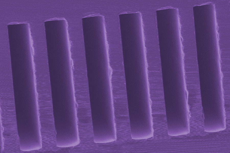
A scanning electron microscope image of the cross-sectional view of the gas chromatograph serpentine channel.
SAM GC-MS
Next Generation Gas Chromatograph Mass Spectrometers
Murray Darrach
Recent years have witnessed significant progress made in the miniaturization of mass spectrometers for a variety of field applications. The main focus at JPL is on the two most common space related applications of mass spectrometers: studying the composition of planetary atmospheres and monitoring air quality on manned space missions. JPL’s miniature quadrupole ion trap mass spectrometer product has been under development for human space flight applications since 2003 and for planetary applications since 2011. NASA has made a significant commitment to this measurement technology on which astronaut lives depend. This technology and its precision, mass, power, and robustness will benefit both human exploration and planetary science.
The Microdevices Laboratory (MDL) has been developing a microelectromechanical system (MEMS) gas chromatograph that is a crucial part of the JPL’s Spacecraft Atmosphere Monitor (SAM). The SAM instrument is a highly miniaturized gas chromatograph/mass spectrometer (GC-MS) for monitoring the atmosphere of crewed spacecraft for both trace organic compounds and the major constituents of the cabin air. The SAM instrument, scheduled for launch to the International Space Station (ISS) in 2019, is the next generation of GC-MS, based on JPL’s Vehicle Cabin Air Monitor (VCAM). VCAM was launched to the ISS in April 2010 and successfully operated for two years.
SAM consists of the miniature quadrupole ion trap mass spectrometer interfaced with a micro-fabricated preconcentrator and gas chromatograph unit (together forming the PCGC subassembly) and a small gas carrier reservoir. The micro-fabricated PCGC unit employs a novel MEMS PCGC technology that is implemented here by combining a MEMS preconcentrator, a microvalve and gas chromatograph chips that replace the macro PCGC components in the VCAM. This significantly reduces the total volume and mass of the gas chromatograph/mass spectrometer instrument from 64.4 L and 37.9 kg (VCAM) to 10 L and 9.5 kg (SAM).
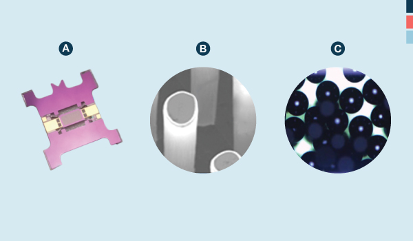
The preconcentrator consists of the silicon doped heater and a Carboxen layer in the chamber (see below). The heater can be flash heated to 250°C in 0.5 seconds due to the thermally isolated design and material of the heater which are made possible by through-etching around the heating plate and a silicon insulator, respectively. The JPL preconcentrator demonstrated more than a 10,000-fold concentration increment for alcohols, which is high enough for analysis of parts per billion concentrations of volatile organic compounds.
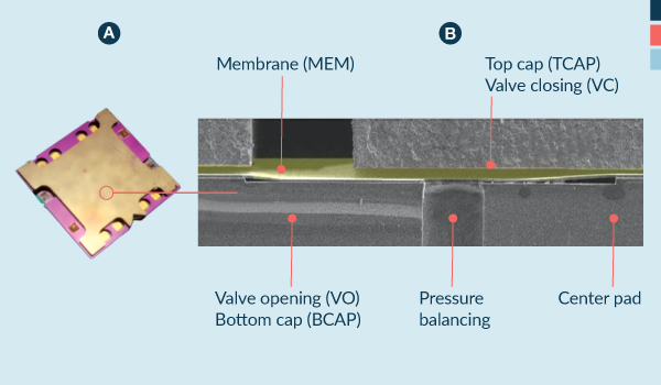
The microvalve is an electrostatically operated microvalve that is composed of three main components: the top cap (TCAP)/valve closing (VC), the membrane, and the valve opening (VO)/ bottom cap (BCAP) (see below). The VC/TCAP and VO/ BCAP are bonded as a stack using gold diffusion bonding technology. The VC/TCAP and VO/BCAP stack sandwich is bonded to the membrane layer using benzocyclobutene adhesive to complete the microvalve assembly. The membrane layer has four membranes embedded, each of which independently moves up and down in response to an applied electric field between the stacks.
These are the first electrostatic MEMS valves to achieve more than a million cycles. In fact, they achieved 47 million cycles before failure, which is equivalent to 5.9 years of operation when the valve is switched every four seconds. Other unique features include the center pad to reduce opening voltage and charge buildup; a pressure balancing mechanism to lower differential pressure across the membrane, lowering stress and allowing the valve to open against high pressure; and an interface treatment to prevent charge buildup, which is the main failure mode of most other electrostatic valves.
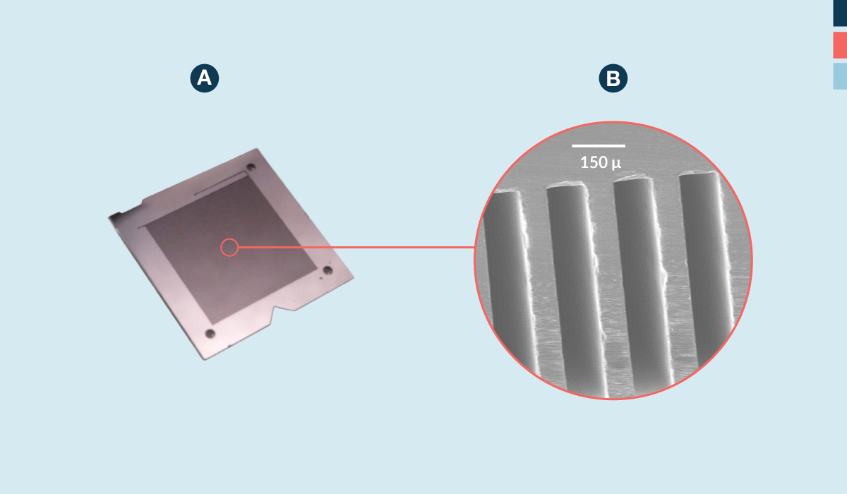
The gas chromatograph microcolumn is composed of multiple stacks of a 1m serpentine column and a capping layer, which are hermetically sealed, by metal diffusion or direct fusion bonding. The serpentine channel generates better separation than that of spiral channel design in the micro level of the chip design. Silicon-silicon layers of microcolumn deliver less tailing and peak broadening than conventional silicon-Pyrex microcolumns due to the higher uniform temperature profile. A photograph of the serpentine channel and a cross-sectional scanning electron microscope image of the bonded serpentine channel are below. The gas chromatograph microcolumn also has a uniform self-assembly monolayer coating along the wall of the serpentine channel which is facilitated by unique coating methodology.
Preconcentrator (A) Thermally isolated silicon heater in the middle chamber where Carboxen adsorbent particles are packed,
(B) Microposts for attaching micro/nano adsorbents,
(C) Carboxen 1000 particles to be packed into the middle chamber that has no micropost.
+ Larger image
Gas Chromatograph Microcolumn (A) JPL gas chromatograph microcolumn,
(B) A scanning electron microscope image of the cross-sectional view of the gas chromatograph serpentine channel.
+ Larger image
Microvalve (A) JPL microvalve chip,
(B) a scanning electron microscope image of the cross-sectional view of the JPL microvalve.
+ Larger image
